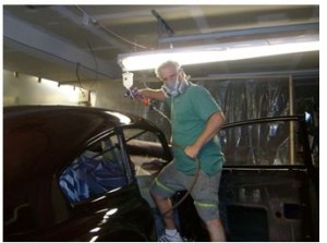
Rege McDonough, a resident of the Steel (and Steelers) City recently wrote to say: “A milestone has been reached! [My] 49 Fastback has officially been painted – Madeira Maroon Metallic. Hope to have it on the road in the spring!!!” The photo below shows Rege hard at work while wearing an impressive paint mask…
Author Archives: admin
60th ANNIVERSARY A LOOK BACK TO 1949
1949 was a special year for Cadillac, although the body design wasn’t changed significantly. The most noticeable difference was the grille. (The single piece windscreen was to be introduced in 1950.) However, engineers had developed a new V8 engine. This was inevitable because compression, an important precondition to improve power and efficiency, couldn’t be increased much with the traditional L-head design. The valves were moved into the heads, resulting in better cooling along with a differently shaped combustion chamber that reduced loss of combustion energy to the cooling system. Despite a small decrease in displacement, the first version of the new engine delivered 10 brake horsepower more. The basic construction underwent light improvements before some design changes became necessary in 1957.
The drawing below shows that the new engine was more compact than its predecessor. This was made possible by a flat water pump and mainly by a new crankshaft with shorter piston rods. Weight was reduced by 220 lbs.
In independent tests a maximum speed of about 100 miles per hour was measured. Acceleration time from 0 to 60 miles per hour was 15.8 seconds. In midyear Cadillac introduced the 62 Coupe de Ville, the first hard top model industry-wide. It was priced at $3,497. The cheapest model (61 Club Coupe) bore a price tag of $2,788, and for $4,839 you could buy the top model Fleetwood 75 Business Imperial. Of 92.554 cars built, 80,880 were registered during the calendar year, resulting in a market share of 1, 67% and 18th place in sales ranking.
Power steering and power brakes (not really essential) were not available in 1949. The optional standard heating system came with only one heater under the front seat, while the costlier deluxe Automatic Heating System had two under-seat heaters. This seems curious today, but don’t forget that until the late 1950s buyers could order a new car without a heater.
The chassis was state of the art: knee action shocks, hydraulic drum brakes, coil springs in front and leaf springs on the rear axle. Buyers could choose between a 3-speed manual transmission and a 4-speed Hydra-matic, both with column shift.
Hydraulic windows and front seat were optional on Series 62 coupes and sedans, but standard equipment on Series 60 and 75 Sedans, the Convertible, the Coupe de Ville and Series 75. The hydraulic pump is essential on convertibles to move the top up and down. The Convertible also came with a full leather interior. (Cloth would soak water in an unexpected shower.)
That 1949 has a special significance in Cadillac’s history is underlined by the fact that there is a special interest group within the American Cadillac & LaSalle Club. This group even publishes its own magazine, the ’49 Times.
Ed. Note: Michael is one of 2 Forty Niners Chapter members in Germany. Besides owning a gorgeous ’49 convertible (which can be seen on page 7 of the March ’05 issue of the Times), he is the editor of “Pre-‘50 Magazine”, a German language publication for enthusiasts of American cars of that era, in which this article first appeared.
HYDRA-MATIC SHIFTING PROBLEMS II: SHIFT LEVER SLOP
Does your shift lever loosely flop from front to back rather than spring toward the front of the car when you remove your hand from it? Maybe your lever is “sloppy” from side to side, too. If so, and your ’49 is not one of the 11 belonging to chapter members with stick shift (as the s lever is different), read on.
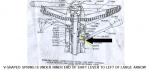
As shown in the drawing below of a similar 1955 Cadillac steering column, the back-to-front position of the Hydra-matic shift lever is controlled by a flat V-shaped spring inside the steering column just under the inner end of the shift lever.
Occasionally, these springs simply snap in two, allowing the lever to merely flop. While you can still shift between N, Dr. Lo and R, it can be very annoying to the driver as it just won’t feel quite right. I recently helped Art Gardner and Frank Lindauer, Times Editor and Editor Emeritus, respectively, install new springs in their steering columns and feel it would be useful to summarize how it was done.
1. Get a new spring. Occasionally, they are offered for sale on Ebay, where Frank got his for $15 or so. Another source is CLC member Joe Alcorn, 111 W. Park Blvd., Westmont NJ 08108-3345, phone:
856-858-8899, who apparently has a stock of them.
2. Disconnect a battery cable so the unwanted sound of your horn doesn’t drive you and anyone else to distraction. Next, remove the horn button by holding the horn ring toward you with one hand, while simultaneously pressing in and turning the button counter-clockwise about 1/3 of a turn to release it. Note that the big end of the cone-shaped spring under the button is toward you. Remove the spring.
3. Remove the large nut that fastens the steering wheel and horn ring to the steering column. Lift off the horn ring assembly. Make two small adjacent witness marks with a punch on the splined steering wheel hub and the steering column shaft so that you replace the steering wheel in the same position when the job is done. Using a steering wheel puller, remove the steering wheel.
4. You have now exposed the innards of the directional signal housing. Looking into it, you will see four Phillips screws that hold the housing to the steering column. As these screws are recessed behind part of the housing and can’t be reached with your fingers, it is best to remove them with a magnetic screw driver. If you don’t have one, you may drop the screws inside the housing after unscrewing them, so keep handy a mechanic’s magnet and a pair of small tweezers to retrieve them.
5. Once the screws are removed, you must pull the doughnut-shaped directional signal housing and the cable attached to it toward you and around the top of the steering column shaft to expose the shift lever housing underneath. You may find that the directional signal cable is too short to allow the housing to be pulled sufficiently toward you and you can’t get it around the top of the steering column shaft. If so, don’t lose your cool, but reach down under the dashboard to the point on the steering column where the directional signal cables enter the column and carefully push them further into the steering column. After playing around with the cables a bit under the dash you should free them up enough at their upper end to be able pull the housing around the top of the steering column shaft and set it to one side.
6. Now, you must remove the shift lever. First, unscrew the chrome cup at the inner end of the lever from the steering column. In doing so you will expose a tapered hinge pin upon which the lever pivots. Using a small punch or Phillips screwdriver, gently tap the pin up from bottom to top (it can only go one way). Remove the pin and pull out the lever. As you remove the lever, note and collect the little anti-rattle springs that flank the lever, if they are present.
7. You should now be able to see the broken parts of the V-shaped spring that you will replace. Pull these out with tweezers. The new spring must be installed with the two V arms facing toward the inside of the steering column. (See diagram above.) You may have to manipulate it a bit and even tap it in with a small punch and hammer. Now, lightly grease the spring, the shift lever and hinge pin, then re-install the lever over the top leaf of the spring. Re-install everything else in reverse order and you are done.
NOTE: the large nut that fastens the steering wheel and horn ring to the steering column must be torqued to 45-50 foot-pounds. Hold the torque wrench in one hand and the rim of the steering wheel with the other.
STOPPING AN OIL LEAK
by Art Gardner
I hate an oil leak. It is embarrassing, frustrating and just plain messy. One of the worst oil leaks on a ‘49 Cadillac is the engine rear main bearing seal, a repair job that intimidates many owners. I know, I suffered with this leak in my 55 Series 62 Sedan (with the same motor) for about 12 years because I didn’t want to take the engine out, but replacing the rear main seal CAN be done correctly with the engine in the car.
The engine in my ’49 6107 Club Coupe was carefully rebuilt recently with the installation of a Teflon-impregnated rope rear seal, which after 500 miles started to leak. The oil pan also seemed to be leaking for two additional reasons: 1. the bolts were slightly loose, which typically occurs after the engine is put back in service and the engine heat shrinks the gasket; 2. the rear pan gasket had been made out of silicon liquid instead of the original cork strip, and it came apart. I repaired everything without removing the motor and it seems to be holding perfectly — no more drips on the driveway! So here is my recommendation on how to proceed:
1. Buy a neoprene (rubber) seal from Terrill Machine in Deleon TX, Olson’s Gaskets in WA or from one of several other Cadillac parts vendors that sell them. Do NOT use a rope seal. Some guys are good at installing the rope seal, but the installation and trimming of the rope to just the right length is CRITICAL. Instead, the modern-style rubber seal provides a true dynamic lip seal and the installation is more idiot-proof. Also buy a quality oil pan gasket set. I like the “BEST” brand for these types of parts instead of FELPRO. Olson’s carries them.
2. Drain the oil, then use a lift or jack the front of the car up relatively high, preferably putting the front wheels on ramps (be sure to chock the rear wheels or put the rear of the car on jack stands);
3. Remove the 2 bolts in the frame holding the idler arm on the passenger’s side of the steering links and lower the center link. Remove the exhaust crossover pipe;
4. Disconnect the battery ground cable and remove the starter (heavy!). To do this, unscrew both of the small wires that attach to the solenoid, noting which one connects to which terminal. Place a rag on the frame rail and rest the starter on it. The positive cable will hold it there satisfactorily, so there is no need to undo any of the other wires;
5. Remove the oil pan and the lower flywheel cover (heavy) to provide working room to get at the seal. Inspect and repair any “dished” bolt holes in the pan — the oil pan surface should be flat. Often, when an oil pan or valve cover is leaking, some ham-fisted mechanic or owner will over-tighten the bolts trying to stop the leak. This deforms the pan or valve cover and ensures that it will leak from now on. If need be, hammer the bolt holes flat with a small hammer and a narrow block of wood to act as an anvil. Re-check for flatness. Use a long, STRAIGHT board with a long piece of sand paper to flatten and re-surface the bolt pattern surface, if desired.;
6. Remove the windage pan, the tray-like baffle bolted to the bottom of the block and the oil pump;
7. Remove the rear main bearing cap. Remove or, better yet, just loosen the 3 middle main bearing caps, leaving the front one alone. (Note the direction the middle bearing caps face if you remove them, as it is important to replace them in exactly the same position.) You do this to let the crankshaft droop just a fraction of an inch or so to slightly free up the upper half of the rear main seal;
8. Screw a slender wood screw into one end of the upper half of the rope seal and grab the screw with pliers. Using a brass, wooden or plastic rod (in order to not scratch the crankshaft journal), push up on the other side of the upper half of the existing rear main seal, while pulling down on the pliers to draw the rope seal out of the crankshaft journal. Once it protrudes out a bit, you can grab the seal itself and pull it with the pliers.
9. Installation of the rubber seal requires no tools — just slip it into place in the upper half. NOTE: the direction/orientation of the new rubber seal is critical. Follow the directions on this that come with the seal.
10. Install the cork strip in the groove/channel in the rear main cap and trim to length, as shown below. Trim it so that the ends of the cork slightly protrude from the end of the cap in such a way that the ends of the cork strip are parallel to the ends of the cap. You want the cork gasket to have some “crush” to it when the oil pan is bolted up. This is much easier to trim before installing the cap (otherwise, substantial trial and error is required). Although probably unneeded, you can place a small amount of silicone gasket sealant on the end of the cork strip immediately prior to final fitment of the rear main bearing cap against the block (before the silicon has a chance to set). Place the lower half of the rubber rear main seal in the rear main bearing cap and orient it according to the instructions;
11. After coating the lower main bearing halves with oil, replace the main bearing cap(s), including the rear cap, and torque them according to the shop manual specifications. Cleanliness is of paramount importance here.
12. Take apart and clean the oil pump. If the lower plate upon which the gears rest is worn, send the pump away for rebuilding. Unless it is broken, I would retain and re-use the same oil pressure regulator relief valve spring, since some rebuilders install a stiffer spring which would increase the oil pressure excessively and maybe cause more oil leaks! Before replacing the pump, fill it with Vaseline so that it is primed and will have pressure when you first start the engine. The Vaseline will then melt away.
13. Install the front cork seal, after trimming to length. This trimming is a careful, slow, iterative process of stuffing it in the groove, noting the excess length, removing the cork, trimming it slightly and test fitting it again and repeating as needed until done. Trim small amounts and sneak up on the final trimmed length. Again, you want a slight crush to the cork seal. Also, you want the ends of the cork seal to be parallel to the machined engine block surface. Here, as contrasted with the rear cork seal, you definitely want to seal the ends (tops) of the cork seal with a dab of silicone sealant just prior to final fitting (and just prior to installing the pan).
14. With the front and back cork seals now trimmed and in place, next test fit the side gaskets and trim them to closely abut the sides of the cork gaskets. Use as little silicone sealant as needed to seal the side gaskets to the cork gaskets. Use gasket sealant to hold the side gaskets in place against the underside of the block while you bolt the oil pan in place. Apply the gasket sealant only to the top surface of the gasket, since it will be easier to scrape the gasket off the machined engine block than off the ribbed surface of the oil pan next time this job has to be done.
15. Replace all parts mentioned in steps 3 through 7. When installing the oil pan, torque it to proper specs (10ft-lbs max). Do NOT over-torque or the pan will distort in the vicinity of the bolts and cause leaks.
16. When you start the motor, the first thing to do is make sure the oil pressure is normal. Then check for leaks. After 500 miles, re-torque all bolts, especially the oil pan bolts. Two of the oil pan bolts are above the starter, which will have to be removed temporarily to get at them.
If the engine has a lot of miles, then it would be prudent to replace the main bearings while doing the rear seal (and won’t cost much). If you were going to do more than just the main bearings and these seals, you would remove the engine, but this job can be done with the engine in the car. There is a trick to “spinning” the top half of the bearings out (using a flattened cotter pin inserted in the oil hole of the crank and turning the crank by hand). Taking off one bearing cap at a time, after installing the new bearings halves re-install and torque the bearing cap back on twice: the first time for a preliminary bearing clearance check with Plastigage; the second a permanent installation.
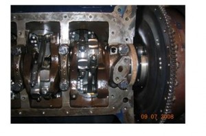
By the way, on a lift this job can be done in 4-6 hours, maybe a good bit less. It took me the better part of a weekend on a creeper since extra time was spent over-restoring some parts (powder coating the oil pan and some bolts, etc). NOTE: A high-quality torque wrench is the key to this job. You probably need two different torque wrenches. A low torque unit for the pan bolts (probably 1/4″ drive” and a stronger one for the main caps (probably 1/2″ drive). The specified torque on the pan bolts (and the valve covers) is so low that there is a substantial risk that you will over tighten them or under tighten them by a good bit if you use too large a torque wrench, with equally leaky results either way. Below is a picture of the rear cap reinstalled, with the cork gasket in place on its underside, just to the left of the flywheel in the right center.
DID YOU KNOW THAT……, Sixty Special Trunk Letters Are In 2 Pieces
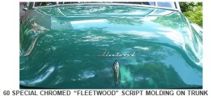
Several articles in the Times earlier this year dealt with the different badges and chrome Vs on the differently- shaped trunk lids of the various 1948 and 1949 Cadillac models. The articles also mentioned that the Series 60 Special trunk lid, on the other hand, is bare except for a script molding spelling out the word “FLEETWOOD”. (See photo below.)
I didn’t give this factoid a further thought until a chapter member recently called me. He told me that to replace the missing script molding on his 60S he bought another that was delivered in two pieces, with the letter “F” being separate from the subsequent letters forming “LEETWOOD”. His question was whether I knew anything about this; specifically, whether the molding being in two pieces was normal or was his purchase unfortunately damaged? Not having the slightest idea, I consulted my 1935-55 Cadillac Master Parts List, which indeed shows the Fleetwood molding to be indeed in two pieces: part number 413 3544 is the letter “F” (cost $1.14 in ’55) and part number 413 3455 is the letters “leetwood” (cost $2.88 in ’55). The same molding is used on 1942 through 1949 60 Specials. We surmised that the reason for this unusual set-up has something to do with the side-to-side curvature of the 60S trunk lid.
HYDRA-MATIC SHIFTING PROBLEMS ON MY COUPE DE VILLE
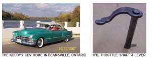
In June 2005 I purchased a ‘49 Coupe De Ville sight unseen on EBay. The car was located south of Houston, Texas, and since I live in Ontario, Canada I had it delivered to my friend Simon who lives in nearby Seabrook TX. I had asked Simon to check out the brakes, steering and general condition of the car. The report came back favorable, so my wife, Kathy, and I decided to fly down from Buffalo NY and drive it home.
When we arrived in Texas we put a few shake-down miles on the car and discovered that the rear end was getting noisy–oh,oh! We agreed that we could not ignore this and pulled the axles so we could remove the differential carrier. We discovered that whoever had replaced the seal had not torqued the pinion nut properly. We re-torqued it to the required 200 ft. lbs., re-assembled and the noise was gone. Kathy insisted that she wasn’t going anywhere without seatbelts, so we put them in the front.
The engine ran well and the car started, stopped and steered well. The Hydra-matic transmission, however, would not shift properly. It would stay in 1st too long, then skip second and move swiftly thru 3rd and into 4th. It also would not downshift unless shifted manually. If held in Lo it would eventually shift into 2nd. We drove it home some 1,750 miles through Buffalo to Beamsville, Ontario. Along the way we stopped in Chattanooga, TN to get a set of Coker BF Goodrich WW radial tires. Boy, what an improvement in ride that made. The car no longer wandered the road grooves and I found myself driving faster.
We did have a mishap on a bumpy freeway in Ohio. The right rear sombrero wheel disc flew off, taking the fender skirt with it. We pulled over and managed to collect both items. The wheel disc was destroyed, but the skirt had only minor scrapes. Checking out the wheel disc once we were home, I found that it was a pre-48 style disc and therefore it did not engage onto the wheel clips far enough to be held secure. We crossed the border without any hassles and brought the car home.
We were busy building a house and shop for the next few years so I did not have time to work on the Coupe De Ville. Finally this summer it was time to do something, so I read section 13 of the ’49 shop manual and put the car up on ramps to adjust the transmission linkage. Part of the reason I hadn’t got to it earlier was that the manual shows a Throttle Lever Checking Gauge that I did not have. I knew that correct linkage adjustment is critical for the transmission the shift properly. Well, I would just have to make do without a gauge and try different adjustments. I disconnected the throttle control linkage from the throttle valve lever, as per fig.149 on page 149, and moved the lever forward and back to find the limits of movement or rotation. To my surprise I could not feel a stop position when moved in either direction. This led me to believe that though the throttle rod lever was moving externally, nothing was moving internally.
I drained 2 quarts of transmission fluid, removed the manual control lever, throttle control lever, and side cover. I then very carefully removed the outer valve body since it houses the inner throttle lever shaft. Before removing the valve body I lifted the car’s carpet and removed the center floor pan with the accelerator pedal so I could see exactly what I was doing and hopefully not drop any parts.
The throttle shaft, shown in Figure 198 on page 175 of the shop manual and in the photo below, has a lever pressed onto it. The shaft has a straight knurl and the end is peened to fix the inner lever to it by an interference fit. The fit had loosened so when the shaft rotated the lever did not move. I brazed the stamped lever to the shaft after indexing it to the proper location. I had a spare shaft to verify the proper location. This spare shaft’s lever had also become loose but had not slipped yet.
I assembled everything, replenished the oil and went for a drive. It shifted into second gear before I reached the end of the driveway, so a big grin appeared and I knew I had solved the problem. I now take every opportunity I can to drive the car as it’s such a pleasure to drive.
2ND EDITION OF AUTHENTICITY MANUAL NOW ON SALE
After more than a year of work by 13 committee members, the 2nd edition of the 1948-49 Cadillac Authenticity Manual for Series 60S, 61 and 62 cars is now on sale. With 123 pages, much more detailed content, as well as 150 mostly color illustrations, this new, improved edition of the manual has more than twice the information on judging and restoring as the 1st edition. Also, being spiral-bound it can be laid flat for easy use. The cost is $65 postpaid. Make your check payable to The Cadillac & LaSalle Club, Inc. and mail it to Bill Anderson, 2198 Johns Hopkins Road, Gambrills, Maryland 21054-1614 USA. Bill can also be contacted by email at rivsrgr8@aol.com and by telephone at 410-849-3376.
In this issue of the Times there are several excellent “how-to” technical articles. In the last issue in September, readers could not have failed to notice that the lead article on the CLC Grand National in New Jersey was lavishly illustrated with two pages of color photos, a Times first. This entailed extra printing expenses for which we thank Times Editor, Art Gardner, for a generous contribution.
It’s that time of year again: 2009 dues are due. If you haven’t yet paid your $8 dues for ’09, you will receive a post card in the mail reminding you to do so. To make a payment, please enclose the post card and an $8 check payable to Jay Friedman in an envelope and mail it to me at: 1530 September Chase, Decatur, Georgia 30033 USA. Canadian members can send me a cheque in Canadian Dollars at the exchange rate of the day for 8 US Dollars. Members in Great Britain and in the Euro Zone can send a 5 Pound or 5 Euro note. If you don’t get a post card, your 2009 dues are paid and you can enjoy another year of the Times, which appears very March, June, September and December, without further ado.
May all Forty-Niners have a Merry Christmas or Happy Hanukah or whatever you celebrate this time of year. Besides the usual Happy New Year, 2009 is significant for Forty-Niners since 60 years ago last month, in November 1948, the first 1949 Cadillacs were sold. So have a great ‘09 as we celebrate the 60th anniversary of our favorite car.
The Wooden Wheel Chock
The Wooden Wheel Chock
Repairing Heater Control Valves
Repairing Heater Control Valves
