Author Archives: admin

NEW PROCEDURE FOR TESTING GAS GAUGE TANK UNITS

Chapter member Joe Foerster found a copy of, as he called it, “a snip” from the Nov.-Dec., 1948 Cadillac Serviceman’s bulletin, as follows:

A PROCEDURE FOR TESTING gasoline gauge tank units, which included lowering the gasoline tank in order to make the tank unit accessible, was announced on page seven of the February, 1948 issue of THE CADILLAC SERVICEMAN. In order to shorten the period of time required to replace this unit, the factory Engineering Department now recommends that the following procedure be used, which omits lowering of the gasoline tank. This new procedure takes less time than that allotted for lowering the tank in the old procedure. The new method is as follows:

1. Disconnect one of the battery cables.

2. Using a standard 4″ sheet metal saw, drill a 4″ diameter hole in the body floor pan directly over the gasoline tank float unit.

3. Disconnect the wiring from the tank unit.

4. Remove the screws which fasten the tank unit to the tank.

5. Lift out the tank unit. The float and arm will come away with it. Test the old tank unit against the dash unit. Failure may have been caused by poor ground.

6. Set the new tank unit with gasket, float and arm in exactly the same position on the tank. Install all screws and tighten securely.

7. Reconnect the wire to the binding post of the tank unit.

8. Fabricate a sheet metal cover for the 4″ hole in the body floor pan. Install this cover, seal with 3-M body sealer and secure it with at least six self-tapping screws.

9. Connect the battery cable.

Joe concludes, “Believe me. Once you’ve done this, you will wonder why the factory didn’t punch a hole there in the first place”.

gass sep 09

newsletter

A BETTER WAY TO REMOVE COUPE DOOR GLASS IT WORKED FOR ME

by Art Gardner

My driver’s side front door glass cracked, necessitating replacement. The 1948 Olds 98 and Cadillac Fisher Body Manual, pages 45-47, sets forth the procedure, which seemed lengthy and complicated. As I proceeded, I realized there is a simpler way, which worked on the front door of my 2-door Club Coupe and MAY work on other body styles, as well as sedan rear doors and cars with power-operated windows.

Everything is done to the inside of the door with the door open. As there are lots of screws and small parts, I suggest using several containers to keep the loose parts organized according to the large parts they fasten.

1. Remove the reveal molding at the top and sides of the window frame. Be careful not to lose the two small pieces of rubber at either end which prevent the garnish molding below from being scratched.

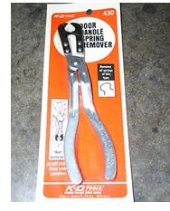
2. Remove the inside door handles and window cranks. Although these can be removed with dental picks or other pointed tools, you will do better to use an inside handle removal tool. I recommend the pliers-type illustrated below. This one is made by the KD Company, but similar tools are made by other firms. The flat-type tool is inferior. (See the body manual for removing the switches on Hydro-lectric equipped cars.)

.
3. Remove the arm rest if a front door.

4. Remove the screws holding the garnish molding below the window to the door. Besides the visible screws, this molding is held to the door by: A. an L-shaped metal hook screwed to the door frame, and;
B. the large heads (diameter: ¾ inch, 18 mm.) of screws which slide into slots in the back of the molding, whose shafts are screwed to the door frame. You have to twist the molding slightly to remove and re-install it. To remove it, you push down on the back end and pull up on the front slightly to get it off the hook. Then, the molding is unlocked from the screw heads by pushing down on the molding while gently pulling it toward you. Later, when re-installing it, you hook the molding over the L-shaped hook with the rear of the molding pushed down to get the large heads of the screws into the keyholes. Once the heads are through the big openings in the keyholes, you pull up on the rear of the molding while keeping the front over the L-shaped hook. Pulling up on the back of the molding brings the heads into the narrower part of the keyholes and secures the molding in place, ready for the small finish screws to be installed. (There won’t be a quiz.)

5. Remove the screws holding the upholstered door trim panel to the door. This panel is also held to the door by several metal tabs that protrude upward and outward from an access panel in the inner door into the back of the trim panel. In addition, the trim panel is held to the door by tracks at the bottom and front side of the door which enclose the corresponding edges of the panel. To remove the panel, gently pull it up and toward the back of the door.

6. As it is now visible, remove the large, square-ish access panel secured to the inner door with screws.

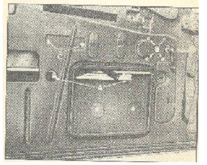
7. Raise (or lower) the window so that two of the four screws that hold the window support channel to the window regulator lift arms are visible through the hole uncovered when the panel in paragraph 6 was removed. At the same time, the second two of the four screws should be visible in the small, round hole to the side of the square hole. See the arrows of letter “A” in the illustration below. Remove the four screws.

8. Lower the glass all the way to the bottom of the door, slipping it past the regulator arms and out from the lower end of the window channels. If the channels are too long to release the glass, it may be necessary to unfasten the lower mount of the divider channel between the quarter window mechanism and the large window and move it slightly to loosen the glass.

9. To make room through the slot at the top of the inner door for the window support channel under the glass, particularly the lower pieces through which screws attach it to the regulator and the rubber molding under the glass, you must now remove the inner beltline fuzzy strip carrier which runs along the length of the top of the door and is secured with a half dozen screws.

10. With the glass now at the bottom of the door and free from the side window channels, it can be rotated 45 degrees or so and eased out of the upper slot in the door.

If the glass is removed this way, you don’t have to remove the divider channel, which is how the Fisher Body Manual says to do it, thereby saving a ton of time and effort. Installation of the new glass (after setting it in the support channel) was simply the reverse.

glass sep09

glass sep09 2

newsletter

GRAND NATIONAL LAS VEGAS

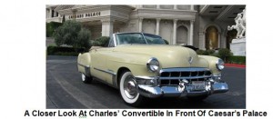
From my hometown of Novato in Northern California, about 30 miles north of the Golden Gate, I toured south to Bakersfield and across the desert with three other cars from our NorCal Regional club: Don Barnes in a ’58 Biarritz, Dave & Patti Ricci in a ’61 SDV and Larry & Jo Ann Brennan in a ’60 Biarritz. We traveled early and stayed overnight in Bakersfield in an effort to beat the heat and make the trip more leisurely. It was necessary to keep the top up on my convertible just to get the shade and cope with 90+ degree heat, but all of us made the trip without a problem. Las Vegas is like an adult Disney World constantly under construction, but I was able to cruise my ’49 up and down the glamorous strip with Frank Sinatra crooning from my boom-box — a long time fantasy come true. Also, seeing the Hoover Dam was awesome — a tribute to what massive projects Americans can build.

The Las Vegas Region did an outstanding job of planning and executing a great event. Having the car show indoors provided a secure, air conditioned space, and the lights really made those Cads and LaSalles sparkle. I was the only entry in my 48-49 judging class. There was a beautiful dark cherry maroon ’48 convertible, but it was entered as display only.

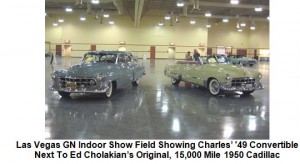
Las Vegas GN Indoor Show Field Showing Charles’ ’49 Convertible
Next To Ed Cholakian’s Original, 15,000 Mile 1950 Cadillac

A Closer Look At Charles’ Convertible In Front Of Caesar’s Palace

Scanning the April of 2008 list of 49ers and the list of people in attendance, I believe ‘49er chapter members attending besides me include Dan Fisher, Ed Cholakian, Frank Stagnitto, Herman Desser and Larry Brennan. There may have been others.

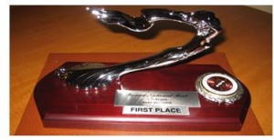
The photo on the previous page is the First Place award I won. Needless to say, I was thrilled even though the competition was absent. [Ed. Note: But, as can be seen in the top two photos, the award to Charles’ gorgeous convertible was richly deserved, regardless of competition.]

I think everyone who drove or trailered a car across the Mojave Desert to Nevada could easily be named a winner just for that effort alone. I left only a small amount behind in the slot machines, and as evidenced by my thorough exhaustion upon arriving back at home, I can definitely state that I had a great time

gnation spe 09 1

g nation spe 09 2

g nation spe 09 3

newsletter

TWO 49s CARRY THE TORCH AT LAS VEGAS GRAND NATIONAL AND WASHINGTON DC AREA NATIONAL DRIVING TOUR

Charles Thompson of Novato, California and yours truly had the only ’49 Cadillacs entered at the CLC’s June 17-20 Grand National and the August 12-16 National Driving Tour, respectively. Though chapter member Ed Cholakian played a major role in organizing the former event and his all-original ’50 Cad won a prize, and member Herman Desser, attending car-less, said “the GN was very well organized and the banquet food was actually very good”, only Charles’ ’49 Cad was actually there. To record these events Charles’ wrote an article on the GN which begins further down on this page, and in the next paragraph I relate my adventures traveling to and participating in the driving tour.

The CLC National Driving Tour’s host hotel at Dulles Airport in a Virginia suburb of Washington is 640 miles from my Georgia home. My 6107 has a manual transmission and within an hour after leaving home Monday, August 10, I noticed my clutch was slipping at low speeds. Realizing the route I had planned to take on Interstate 81 to I-66 was replete with hills, if not mountains, discretion dictated that I adopt Plan B and travel via a relatively flat route on I-85 to just south of Richmond VA and then I-95 to Dulles. This temporarily resolved the clutch problem, since it did not slip at higher speeds, but made for a hotter than anticipated 1½ day drive. (Wife Elaine wisely went by air.) Nonetheless, the driving tour was a success. Some 40+ cars and their owners visited many of the great monuments in Washington, toured surrounding areas, including one of my favorite places, Harper’s Ferry WV and finally spent a memorable day at George Washington’s home at Mt. Vernon. Since no other tour car had any problem whatsoever, mine won the “Hard Luck” award by default. I made it home OK and am now busy fixing what’s wrong.

newsletter

CONVERSION OF AIR CLEANER TO USE A PAPER ELEMENT

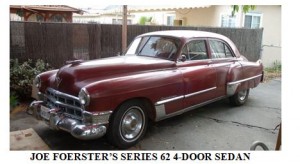
Joe Foerster of N. Hollywood CA has converted the oil bath air cleaner on his Series 62 sedan to use a modern paper element. He did the job in such a way that it is not visible. Joe put together a series of photos and descriptive text regarding the air cleaner’s conversion which can be found at the following web site: http://bobnjoe.com/car/1949/blog2/archives/2007/11/entry_125.html Below is a picture of Joe’s car, appropriately named “49er”, with its converted air cleaner ensconced under the hood.

air cleaner jun 09

newsletter

COME BLOW YOUR HORN

by Art Gardner

Installing my 6107’s horns was one of the last tasks to complete after getting her running. I hooked up the wires to the horns, relay, etc and tried out them out. They blew for a second or two and then quit. So I had to take the horns off and give them a “tune up” by taking them apart, filing the points (using an ignition points file), cleaning them up internally, adjusting the points to give a consistent tone, painting, etc.
The task of adjusting the points is a bit irksome, as it will annoy the neighbors! Basically, you turn the adjustment nut while energizing the horn with a couple of wires until a good sound comes out of the horn. After reinstalling the horns, all that was left was to install the horn button and horn ring. That job took a little bit of patience in order to make the system work reliably, as described next.

To get the horn ring and button working right, I first had to adjust the longitudinal position of the steering shaft relative to the steering column. This was because I had changed this positioning inadvertently as part of the installation of a rack and pinion steering unit. This is not necessary on cars with stock steering.

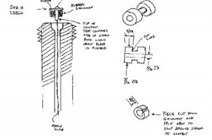
Next came the task of trying to find the right replacement for the fiber washer that originally was fitted under the little contact at the top of the steering shaft. As you can see in the schematic below of a generic Cadillac steering wheel, the horn button (7.3785) is held away from the steering shaft by a conical spring (7.3796) which rests at its small end against the nub of the contact (7.3820).
The contact has a flange and a shank (not seen in this parts diagram). I thought that the horns were energized by the flange of the contact touching the top of the steering shaft. But that is not the usual manner of blowing the horn. Instead, the flange is held slightly away from the top of the steering shaft by the washer, even against the force of the horn button spring. When the horn ring is pushed, it causes the contact to tilt slightly in the same direction as the horn ring. The lower tip of the contact apparently then touches the inner wall of the steering shaft, completing the circuit. See my sketch (not to scale and a little rough, but you will get the idea). The trick then is to come up with a decent replacement for the washer that will be thick enough to keep the flange from contacting the top surface of the shaft and yet will allow the horn to blow when the horn ring is tilted. Jay Friedman told me that some folks take a small rubber band and wrap it around and around the shank to make a replacement. I tried that, with poor results. The car had an O-ring on there as some previous owner’s attempt at a repair, but it wasn’t doing the job.

june 09 horn1

june 09 horn2

What I came up with is a bit of rubber grommet as shown in the drawing above. I cut the grommet with a scissors to make a suitable collar to wrap around the upper part of the shank of the contact. To slip it over the shank without removing the horn wire from the shaft, I simply sliced it lengthwise (split it) with the scissors. Since it is captured in the bore, the split in the rubber is of no consequence. I found that a grommet with a 3/16″ ID worked well. Alternatively, a bit of rubber hose with a similar diameter would work as well. It takes some careful trial and error to get the length of the rubber /grommet just right, but I managed in 4 attempts. The set up works well and my car has working horns for the 1st time in 2 decades

newsletter

A 49 IN SWEDEN

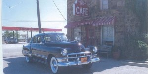
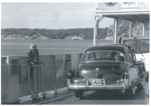
Chapter member Lars Pettersson now lives in County Galway, Ireland but owns a ’49 back home in Sweden. Lars writes that it’s a “4-door, Series 62 Touring Sedan, black, with 42,363 original miles as of April 2008”. The photo below shows Lars’ car on a ferry crossing a Swedish fiord at Lysetil. The little boy, naturally, is much more interested in the water than the car. He’ll see the light when he’s older!

sweeden 09

newsletter

HOW TO HOOK UP YOUR 49s UNDER HOOD HEATER HOSES

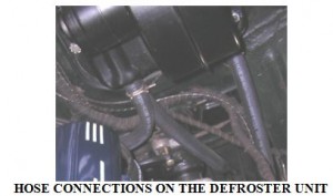
Before hooking up the hoses, observe that the defroster core and motor on the driver’s side firewall has three pipes pointing downwards. Two of these pipes are on the inboard side of the defroster, one of which is in front of the other. The third pipe is at the outboard side of the defroster.

Directly under the defroster, sitting on the frame rail, is a T shaped pipe fitting (to which hoses will be connected). The T connection sits on the frame in an upside down position, something like this ?, with the axis of its bottom facing longitudinally toward the front and back of the car.

From the pipe connection at the back of the driver’s side cylinder head, a short hose goes through an L-shaped elbow pipe (which looks like this: ?) to the front pipe of the two inboard pipes on the defroster. From the back pipe of the two inboard pipes on the defroster, another hose runs under the car’s body to the driver’s side under-seat heater. A third hose runs from the outboard pipe on the defroster straight down to the upward facing pipe on the ? (or T) connection. (See the photo on the next page.)

From the second pipe on the driver’s side under-seat heater, a hose runs across the top of the frame to the passenger’s side under-seat heater. From the second pipe on the passenger’s side under-seat heater, a hose runs back over the frame to the driver’s side of the car’s underside, and then all the way to the backward facing pipe on the ? (or T) connection. Another hose runs from the front facing pipe on the ? (or T) connection, up through a clip on the inner fender, to the pipe on the left side of the water pump.

june 09 heater

newsletter

MY COURTSHIP WITH THE BARONESS

It all started innocently enough, as many “romances” do. In October, 2008 I decided to drive my ‘49 Club coupe, The Duchess, to the annual Cadillac Day held at Norwood Cadillac in Norwood, Mass. It was a picture-perfect New England fall day, resulting in a large turnout of vintage Cadillacs and LaSalles.

As I sat by my car enjoying the festivities and the last vestiges of the old car season, an older gentleman approached and struck up a conversation. He obviously liked my car, mentioned how he had always loved the 1948-49 “fastback” coupes, and said he owned a 1949 Cadillac Series 62 4-door sedan that he was considering sending to the crusher. He further explained that while the car had lots of rust-out, it did have many new parts, including brand-new rear leaf springs and shackles as well as a new battery box, that the water pump, carb and generator had been rebuilt, and that it ran and shifted perfectly. The die was cast; I obtained his address and promised I’d take a “look” at it the next day.

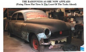
I arrived at the appointed time, and as I drove up his driveway I caught my first glimpse of “Her” sitting forlornly beside his garage. I was anxious to examine this derelict, and wasted no time doing the requisite “walk-around”, opening the hood, doors, trunk and peering underneath. She was indeed a rusty one: the “tin termites” had enjoyed an all-you-can-eat buffet, in the process devouring both inner and outer rocker panels and the bottom front and rear sections of the front fenders. The rest of the body had ample surface rust and peeling paint, but the intriguing aspect was that this appeared to be a totally original unmolested car, right down to its original paint, Avalon Grey. In addition, amazingly enough, the doors were rock-solid as was the trunk and, except for the front corners, the floors. He started her up and the engine sounded strong. A lot of accessories still worked, including all the interior lights, and the car was 100% complete, right down to the original washer bottle and perfect vacuum antenna sitting in the trunk.

He wanted $1,000 for it, but when I waved $800 cash under his nose the deal was done. The next weekend a fellow Cadillac enthusiast and I brought her home on a trailer. I gave her an interim name, The Grey Ghost, and started her up every day after work. The more I ran her the better the engine sounded! I started feeling pity for the poor girl (a dangerous emotion) and before I knew it she was in the garage and up on jack stands. I rebuilt the brake system, reasoning, against everyone’s sound advice (including my own) that, perhaps, there was a glimmer of hope for this rusty relic, and doing most of the work myself I’d possibly transform this “diamond-in-the-rough” into a fun “driver”. Yeah, right! I further rationalized by telling myself I had many of the parts she needed and five other ’49 four-door sedan parts cars.
I finished the brake system and commenced completely disassembling her. I found it utterly amazing that most everything came apart with relative ease, especially considering her rusty state of disrepair. When I pulled up the original carpets, I even found an interesting assembly-line checklist glued to the rear passenger area floor! I had never seen one of these in the many ‘49s I had already restored or parted out.
The disassembly progressed at a feverish pace. (Even as a kid I loved taking things apart. The hard part is putting it back together!) Before I knew it I had a bare shell on a chassis. All the stainless moldings even came off as though they had been installed last week; not one clip was rusty or broken.

A few weeks later, pondering where I might locate better fenders, I remembered a ’49 sedan I had previously owned which ended up inside a trailer at a local salvage yard. On a whim, I called the yard, whose owner told me the car had not moved, was now disassembled and had lots of spare parts in it. We agreed upon $600 and this gem was hauled to my yard to join the others.

After discussing it with The Duchess, I decided that, in keeping with the regal theme, her final name would be the Baroness. I contacted the guy whose name was on the title, and learned that he had driven her daily for 3 years, and it was not uncommon to have her up to 90 mph! He was thrilled to learn she finally had a good home and a prospect of salvation.

My auto-body man and I have put in many long weekends already, and the Baroness is now rock-solid. I lost track of how many patch panels I fabricated to bring her to this point; my auto-body man even suggested I name her “Patches” instead.

All the upholstery is being redone in grey Bedford Cord with blue Broadcloth and blue carpets, which is 1949 Cadillac trim number 41. I’ve always been a stickler for authenticity, but this time I’ve decided to deviate and paint her a 2-tone color, Triumph Blue on the bottom with a French Grey roof. Instead of “sombreros”, I’ve decided to install the small “standard” hubcaps with trim rings. Finally, I’m going to do the dash like a convertible: Triumph Blue Metallic with a Beach Beige insert, which I think is going to be a striking color combination.

The Duchess is really excited abut her new sister, and I plan to show them side-by-side at future shows. Projected date of completion is Spring 2010
baroness jun 9

newsletter